Overview
I integrated the wiring and designed the enclosure for the charge-cart battery management system, connecting the battery management unit (BMU), commonly known in the industry as the BMS, to the high-voltage breakout board (HVB) so the pack could charge safely and consistently.
The work tied together signal-level design, physical routing, and safety requirements. It had to preserve the interlock loop behavior, maintain clean CAN and fault-sensing paths, and keep everything serviceable inside a practical enclosure for use in our shop and at competition.
Wiring Overview
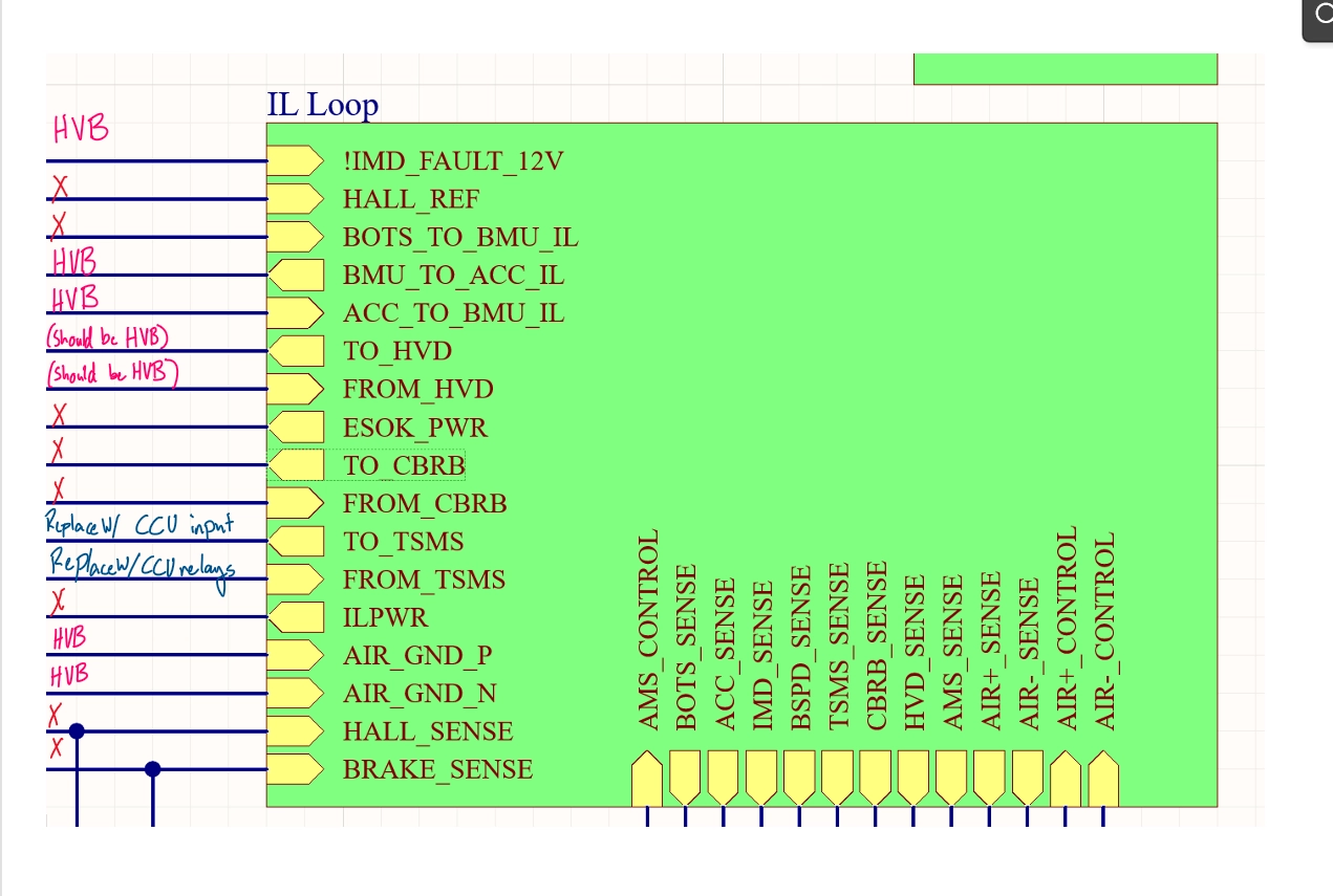
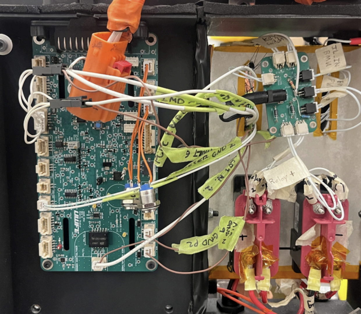
The wiring schematic defined how CAN, interlock, and fault-sensing signals needed to flow between the BMU and HVB. Using that as the reference, I built the harness and routed each connection to minimize cross-talk and make future diagnostics straightforward.
Interlock loop signals from the HVB are brought into the BMU and shorted internally when safety checks pass, enabling high-voltage charging only when the pack and charge cart are in a safe state.
Enclosure and Charge Cart
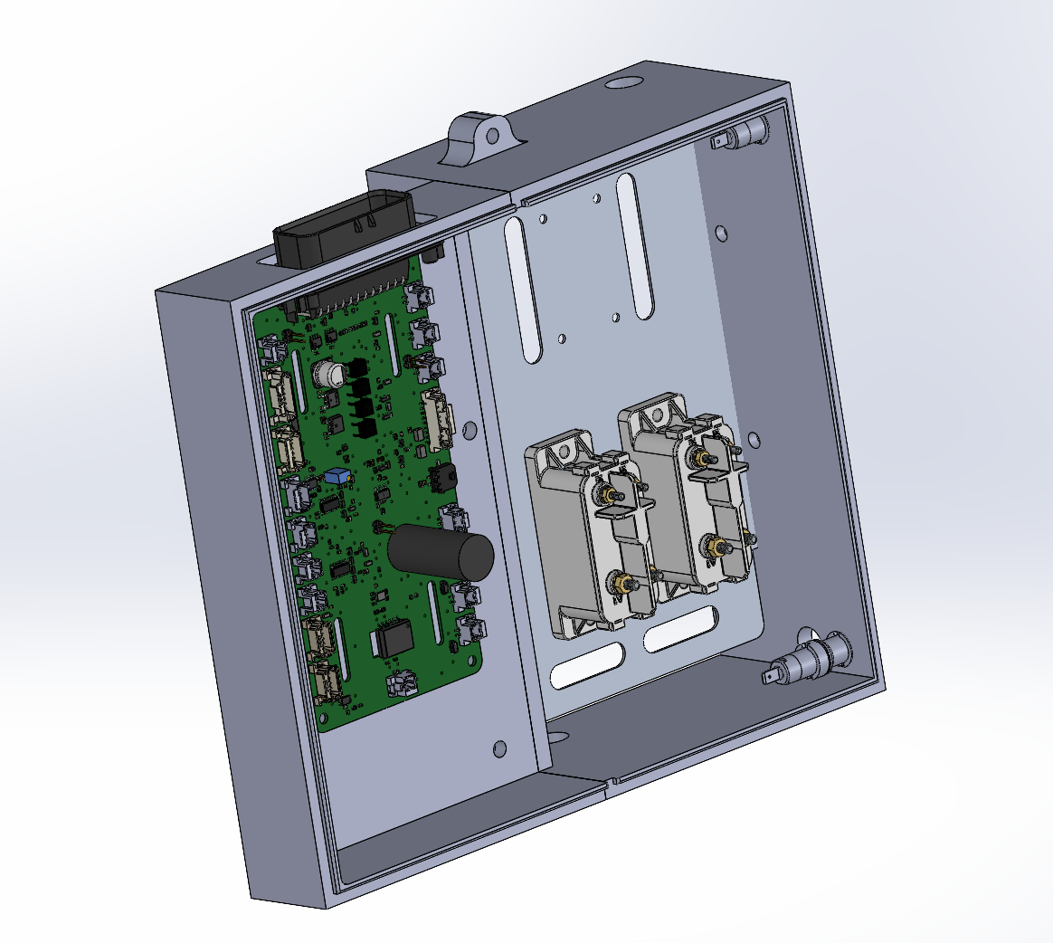
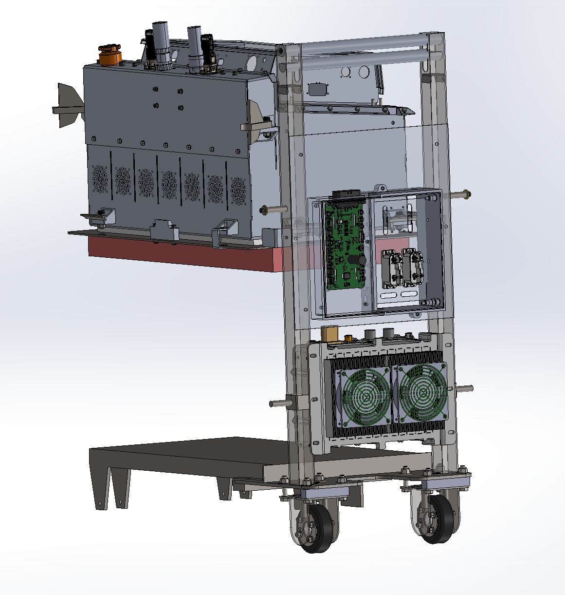
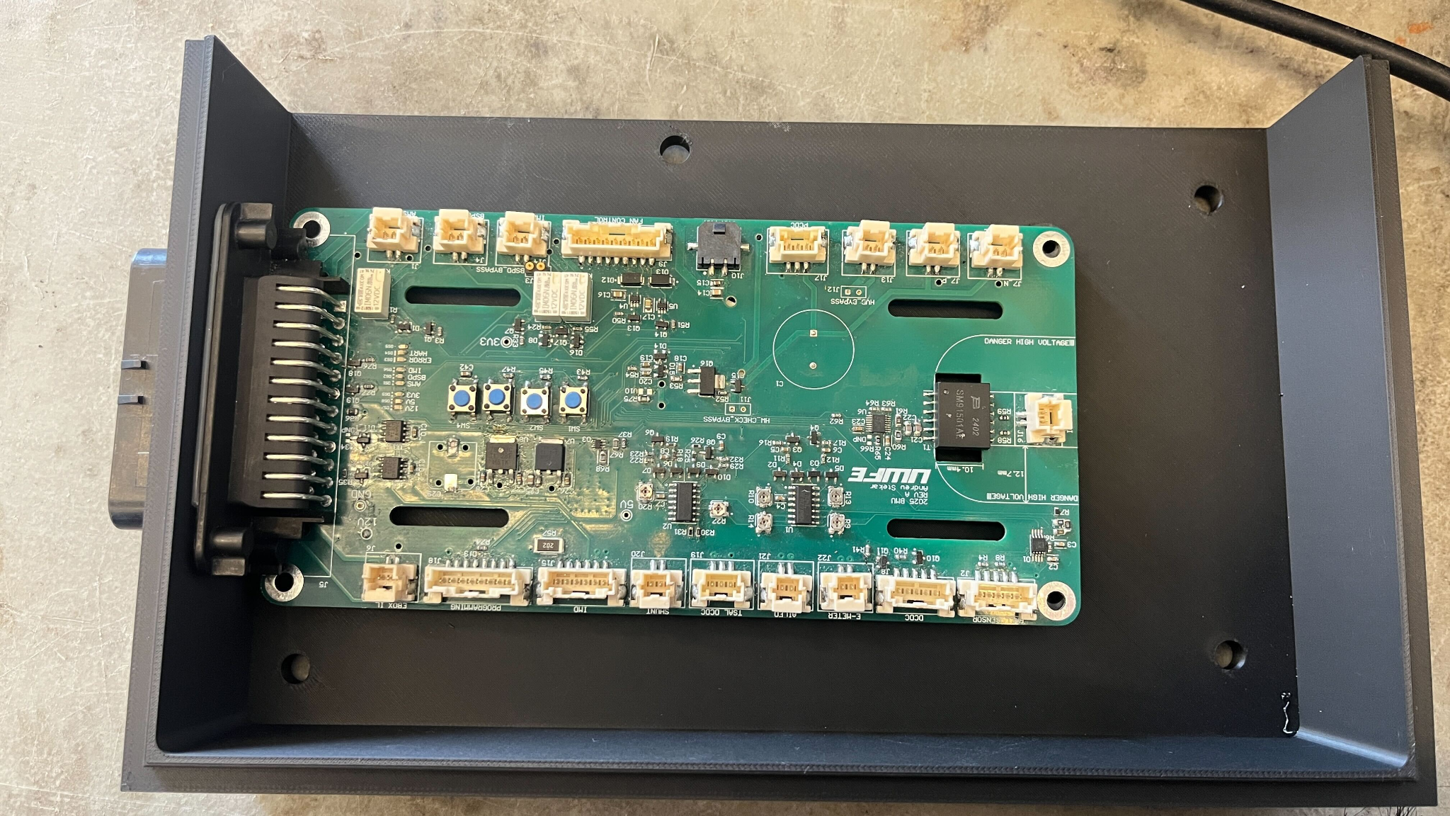
I used CAD models to plan how the BMU, HVB, and wiring would sit inside the enclosure and on the charge cart. This helped choose mounting points, cable entry locations, and clearances for connectors and strain relief before committing to hardware.
The final enclosure balances accessibility and protection: it keeps the boards secure and shields the wiring from damage, while still allowing the team to probe signals, inspect connections, and modify the system as needed.
Outcomes
- The BMU reliably received interlock loop information from the HV breakout board during charging.
- The battery pack was cleared for high-voltage charging after all safety checks and signal paths were confirmed.
- The integrated charge-cart wiring and enclosure passed electrical tech inspection for the 2026 Formula Hybrid+Electric competition.